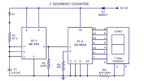
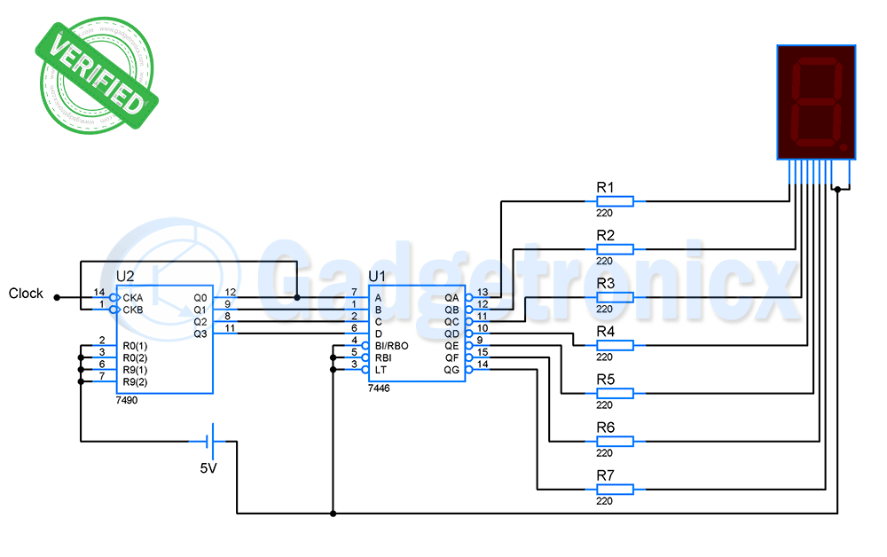
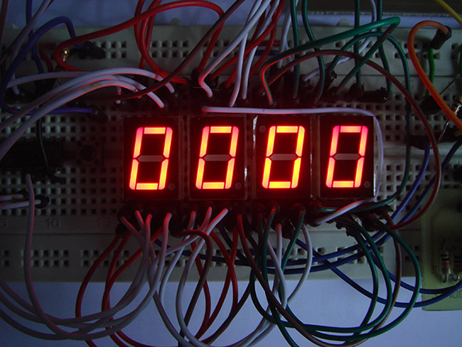
Circuit above is used to display counts in 7 segment display.Here we are employing two ICs and 7 segment to perform this action.IC1 NE555, IC2 CD 4033 and a seven segment display LT543.As we know IC 555 is a timer IC and CD 4033 is a simple decoder IC which is commonly used to drive 7 segment displays.Lets move into the working description of this simple counter display circuit.
WORKING OF THE CIRCUIT:
Here NE 555 was wired as Astable Multivibrator which is capable of generating a square wave the period of the square wave was determined by means of external component RC connected to IC 555.The Astable Multivibrator does not require any external trigger , it is capable of generating continuous square wave pulses.The output pulse was then given to the input of the IC CD 4033.
For each pulse the output of the CD 4033 advances by one count.The output of the IC2 in the circuit was wired to the 7 segment a,b,c..g as shown in the figure.Then the pulse from the decoder lights up the seven segment on a sequence there by working as a counter display.The switch S1 was used here to initiate the counting.Diode D1 was used here to prevent the risk of accidental polarity reversal.The given 7 segment display counter circuit can be employed where the process of counting events was needed under controlled environment.


How can I dispaly numbers upto 25 using this circuit?How many ICs and displays are needed?What are the modifications to be done in this circuit for displaying numbers upto 25?
hi..can you send me the documentation of electronic auditorium counter using ic 555 and ic 4033 .
i am doing study project on that .That information may help for my research/project.
Apoorva,
Here is it//www.ltoxd.com/people-object-counter-circuit-diagram-ic555/
Can we convert it to a voting machine?How if possible?
Andy,
It's not possible, you have to use a Microcontroller to build a voting machine or robust circuit to do so.Here is a link where is used 8051 microcontroller to build a voting machine
//www.ltoxd.com/simple-voting-machine-using-8051-microcontroller/
@frank donald i want to work the seven segment LED display with manually can u help
Satheesh,
Manually in the sense without multivibrator and decoder IC right?Yes it is possible all you have to do is connect switches each pins of the 7 segment and turning the segments on using switches based on your need.
The circuit is not working properly it shows all the segments on.
Run a check whether you made connections correctly, if you still facing there might be a problem with in Mulvibrator part
The circuit works beautifully…… effort is much appreciated.
Thank you keep visiting…
@frank, I'm working up a timer using the example you created here://www.ltoxd.com/2014/05/two-digit-counter-circuit-7segment-ic-4026.htmland want to put it in Astable Multivibrator mode, for use as a second timer..what changes need to be made – also curious about the resistors on the display leads..thanks for the great work and examples!
Its simple all you have to do is remove the push button and connect the pin 2 to pin 6 of the IC.While working in Astable mode you need to consider the time interval so i suggest you to do with proper calculation.Thank you for the compliment and keep visiting….
@frank donald, I usually see resistors at each leg of the 7 segment display, but there not shown in your diagram.Are they needed here or does the IC handle that?
Its always safe to use a current limiting resistor and i recommend you to go for 470 ohm resistor above
@Yusuf Ok dude i can help you.But i need to know what problem you are facing in the above circuit?
the circuit is not working pls wat n want can I do to get it work cos am defending it tomorrow pls u can reach me onaderemiyusuf@yahoo.compls dear circuittoday