|
| Audio Amplifier using IC LM386 |
Amplifiers are used to boost the strength of an input signal and should give an amplified version of the signal in output.Audio amplifiers are widely used in Stereo or Home theater systems, Mini speakers etc.There are numerous ways to build a Audio amplifier circuit but nothing is efficient as building using a dedicated Audio amplifier IC.This circuit uses most simple and cost effective chip LM386 to build an Audio amplifier.
IC LM386:

|
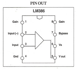
| Pin diagram of LM386 |
LM386 is a simple low power audio amplifier used in most of Audio circuits for its less power consumption.This IC is capable of giving an output gain of about 200 when external components are used along with it.But when you use it without adding external components its capable of delivering amplification of 20.
The pin 1 & 8 are meant for altering the gain level by tying up a capacitor or RC pair in between them.Audio input was fed through Non inverting input pin while inverting input tied to the ground usually.
WORKING OF AUDIO AMPLIFIER CIRCUIT:
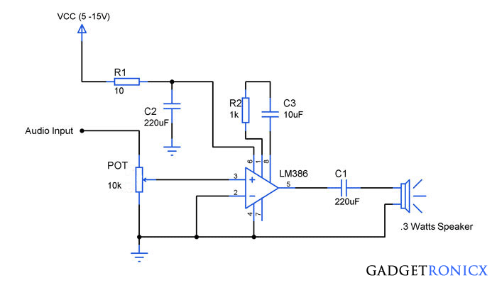
The LM386 powered by Vcc uses resistor R1 and Capacitor C2 along with it.This is to prevent oscillations in the circuit.The Resistor R2 and Capacitor C3 plays a major role in above circuit as it alters the output gain obtained in output.Adding a single capacitor of 10uF will help us to obtain max gain.While using along with resistor R2 will help you obtain a gain of about 50db.The positive terminal of C3 should be connected to pin 1 and negative to pin 8 of the IC LM386.
Capacitor C1 was used to couple the output to speaker and POT can modify the gain of output signal.Set high gain with LM386 when voltage level of input signal is extremely low.You can feed any Audio signals to this circuit and this works just fine to do its purpose.
PCB DESIGN:
 You can download the Gerber file for this PCB design below.


Good day .If you want more amplification, will it be wise to take the out put of the amplifier and amplify it?
The "working" section referst to R3 but no component in the diagram is called out as R3.Also, no polarity is shown for C3 — which end is positive?
I apologize for the error, the article was now updated with precise information.The positive of the C3 should be connected to the pin 1 and negative to the pin 8 of the IC LM386