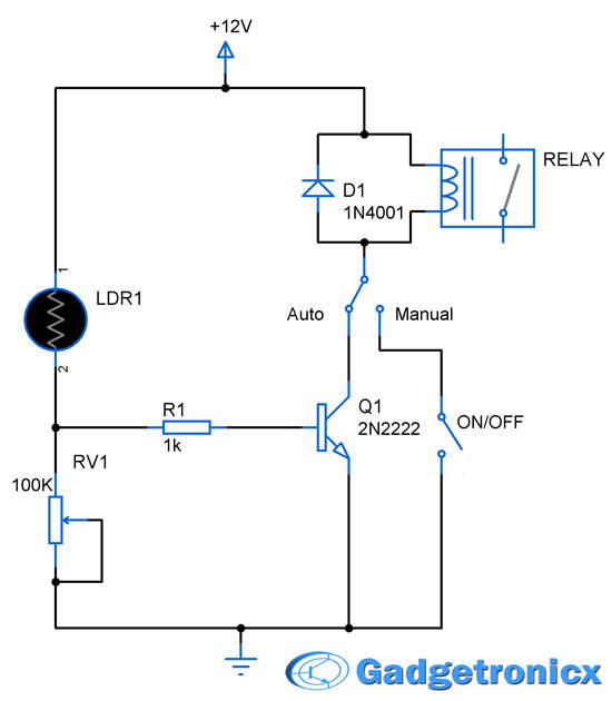
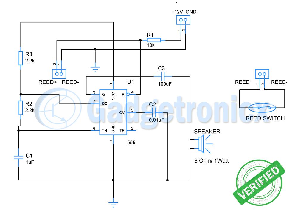
Garage door lights are very essential and it can be a pain when we switch it on and leave without turning it off.This leads to wastage of power and our energy.Automating the garage lights can be a solution for this problem.The above circuit was designed to automate the garage lights
WORKING OF AUTO GARAGE DOOR LIGHTS:
A reed switch and a NOT gate forms the main constituent of this circuit.A Reed switch is something in which the conductors come into contact when a magnet is brought nearby.Thus providing conductivity to the flow of current through it.The logic here is to fix a simple bar magnet to the bottom of the garage door and set the reed switch at a place where the door comes close to it when shut.I have added a simple animation demonstrating the working of reed switch for better understanding.
The rest of the circuit is self explanatory.Therefore reed switch provides electrical contact and logic high input to NOT gate when door is closed.The NOT gate in turn gives logic 0 as output which keeps the Lamp in off state.When Garage door is opened the reed switch opens disconnecting the contact and NOT in turn gives logic 1 as output.This in turn drives the MOSFET to drive the lamp connected to it.
NOTE:
- This circuit can be used in other places such as cupboards, shelves etc.


how can i use a water flow sensor using hall as an on/ off switch.?
Joe,
You need to use a Microcontroller for that.As far as am aware Water flow sensors give out pulse input which cannot be handled by the above circuit.