LCD modules are widely used to display calculated data's, user references and much more.In addition all character based LCD which uses HD44780 controller consists of a special RAM known as CGRAM which allows user to create custom patterns.This tutorial will teach you to create your desired pattern as well running it as a simple animation.
CGROM:
CG ROM is nothing but a memory which holds the pattern of the characters as predefined lcd font.Ever wondered how LCD displays the corresponding font when you pass the ASCII value of a particular character.This job was done by means of this CGROM memory.
DDRAM:
CGRAM:
CGRAM is the memory in the LCD module which allows user to create custom characters by rewriting the character patterns in the program.Generally we will initialize the LCD by using "0x80" command which will point the DDRAM address and from there the LCD allows us to display predefined characters which is stored in the CGROM.
In order to create custom pattern we should initialize the device to point the CGRAM address ranging from 0x00 to 0x07 in the LCD.This can be done by using the command "0x40", which forces the device to point CGRAM address.Refer the instruction set of LCD for better understanding.Remember there is a difference between instruction "0x40" and address "0x00" try not to get confused.
So whenever you writes the instruction 0x40 it will allow us to create the predefined character in the CGRAM address 0x00.The command 0x48 will allows us to store the pattern in the address 0x01.In this way we can create up to 8 character patterns.So we now know what is CGRAM and how to initialize it for storing our custom character.Now lets see how to create the pattern in it.
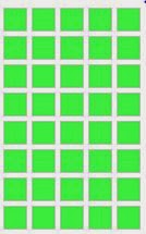
The above block represents a single elements of an LCD and it contains 5 columns and 8 rows in it.And we are going to create pattern by sending corresponding byte for each row.For example we need to make first three columns to lighten up then we should send "XXX11100" byte to the LCD, the first three bytes are don't care.Next we should do the same for the remaining rows.So after sending 8 bytes of data we will finish up with storing a Custom pattern in the CGRAM address.For next pattern we should move on to the next address with instruction 0x48 and so on.
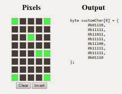
Here is a Custom generated Pac man icon using a simple web tool.Not to worry it looks lot better while displaying it in the LCD.
So we are now done with the chracter generation and all its left now is to display it.It can be done by using calling the CCRAM address as data in the program lcd_data(0x00,1) will print the pattern you have previously stored in the CGRAM address 0x00 by using the instruction 0x40.And 0x01 will print the pattern you stored using the instrcution 0x48 and so on.
STEPS TO CREATE CUSTOM PATTERNS :
- Initialize the LCD as you do it generally.
- Pass the command 0x40 to point the CGRAM address.
- Now create your desired custom pattern by using the above method.
- After finishing your pattern return to the DDRAM location by giving the command 0x80 to the LCD.
- And now print the pattern in any location by passing the CGRAM address 0x00,0x01 to 0x07 as data (i.e with RS pin high state) to the LCD.
- You will get your pattern now.
ANIMATING THE PATTERNS:
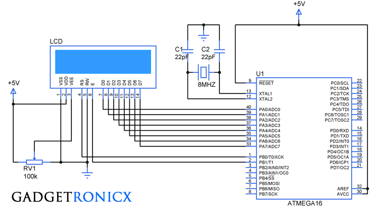
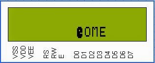
Animating the patterns is not a big task create some of your desired patterns and program it to display the patterns in a sequence and you will get your animation.For example i have created two patterns of Pac man one is normal icon and another one is with its mouth wide open.All i am going to do it display these two patterns one by one in a sequence with specific delay.Through this am going to make it look like eating out the word "WELCOME" in the lcd, Sounds cool isn't it.
CODE:
#include

           #define F_CPU 8000000UL  #include

            unsigned char font1[8]={0x0F,0x1E,0x1C,0x18,0x18,0x1C,0x1E,0x0F}!unsigned char font2[8]={0x0E,0x1F,0x1B,0x1F,0x1C,0x1F,0x1F,0x0E}!unsigned char word2[]={"WELCOME"}!int i!char position;      void lcd_data (char a,int b)       //LCD routine  for data and command  {     PORTA=a!if(b==0)      {        PORTB&=~(1<<0)!}     else       {        PORTB|=(1<<0)!}     PORTB|=(1<<1)!_delay_ms(2)!PORTB&=~(1<<1)!_delay_ms(2)!}      void lcd_init ()      {          lcd_data(0x3C,0)!// 4-bit mode - 2 line - 5x10 font.lcd_data(0x0C,0)!// Display cursor with blink.lcd_data(0x06,0)!// Automatic Increment - No Display shift.lcd_data(0x01,0)!lcd_data(0x02,0)!//Clear screen and return home                  }     int main()  {       DDRA=0xff!DDRB=0x03!lcd_init()!lcd_data(0x40,0)!for(i=0;i<=7;i++)       {         lcd_data(font1[i],1)!}       lcd_data(0x48,0)!for(i=0;i<=7;i++)       {         lcd_data(font2[i],1)!}       lcd_data(0xc5,0)!for(i=0;i<=6;i++)       {         lcd_data(word2[i],1)!}       i=0!position=0xC4!while(i<=6)                //Pac man eating out the letters animation sequence       {        lcd_data(position,0)!lcd_data(0x01,1)!//Displaying first pattern        _delay_ms(150)!lcd_data(position,0)!lcd_data(0x00,1)!//Displaying second pattern with delay        _delay_ms(300)!lcd_data(position,0)!lcd_data(' ',1)!i++!position++!}       lcd_data(0x01,1)!return 0!while(1)!}
WORKING VIDEO:
NOTE:
- Use 5×10 matrix to use the complete pixel for your pattern.
- Specify appropriate time delay when running your pattern as an animation.
- Working video of this animation will be added shortly.




what is port A,B AND DDR AND HOW ARE THEY DEFINED
Hi,
I have used AVR studio in which "PORTA" is mapped to the address of Port A of the microcontroller.Whereas DDR is used to set direction of the port.