|
| Digital Code locker system using 8051 |
Microcontrollers form the most significant part of several security and surveillance systems which plays an important role in ensuring safety of our priced possession.Here we are about to see the Embedded design and programming of a Password based Digital locker system using 8051 Microcontroller.Despite the simple look this system can handle intrusions to offer high protection and also alerts the user in case anonymous person tries to break into the system.
16 x 2 LCD:

|
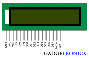
| 16×2 LCD Pin diagram |
16 x 2 LCD is most commonly used display in many applications, it consists of a 16 columns and 2 columns hence got the name 16 x 2 LCD.The LCD consists of a Data register which is used to write the data to be displayed and a Command register used to write the instructions needed to the display.I have written a brief article onProgramming and Interfacing LCD with 8051 Microcontrollerkindly take a look before getting started with this project.
4 x 3 KEYPAD:

|
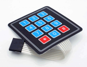
| 4×3 keypad |
The keypad part of this project was used to feed password input and to initialize the system.So I have used a 4 x 3 configuration keypad a total of 12 keys in it, you can increase the number of keys by altering the program and design.ReadProgramming and Interfacing of Keypad with 8051 Microcontrollerto obtain complete knowledge about it.
DESIGN OF DIGITAL LOCKER SYSTEM:
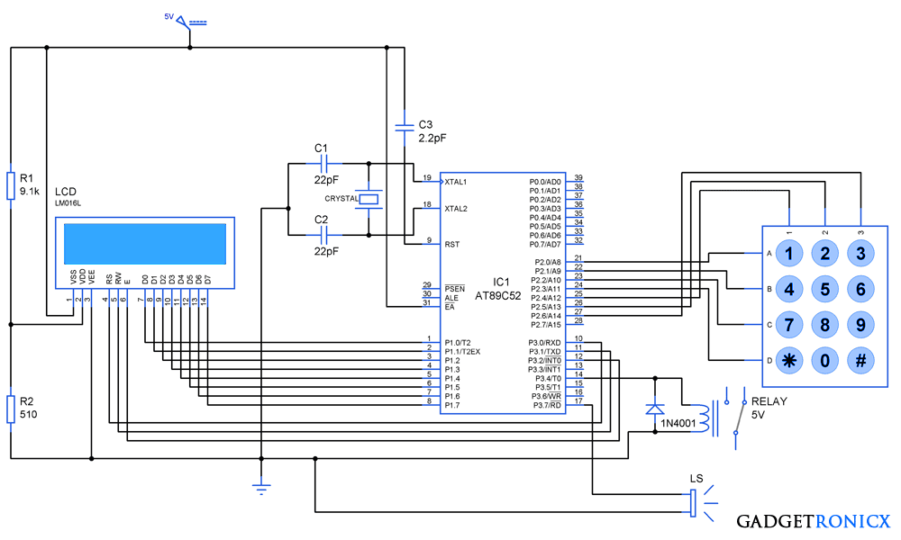
This system comprises a bit complex design in order to protect the safe from intruders and alarm the user in case any breach was detected.Therefore the design of this system comprises of three basic steps, they are
INITIALIZATION:
- The system needs to be initialized by pressing the "*" key in the keypad.
- This locker will not respond to any of the key press before initialization using "*" key.
- It will Turn ON the LCD and count of trials is initialized to zero.
- A command "Enter Password" in the LCD and blink of cursor will convey that the system is ready for password input.
PASSWORD INPUT:
- The strength of the password in our system is 4 characters.
- The password input can be fed into the system by using keys from 1,2……9
- As soon as you enter four characters controller will verify if the entered password matches with the system password.
- Based on the password verification by the controller there will be two cases totally.
CASE 1:
- If the password matches, LCD will display as Message "Locker Open" and relay will gets activated.
- After the usage of the protected locker, you need to turn off the system by means of pressing "#" key in the keypad
- The relay as the system will gets turned off.
CASE 2:
- If the password doesn't match , LCD will display a Message "Wrong Password" in it.And the trial count will be incremented by one in the microcontroller.
- Then the user have to initialize the system by pressing "*" before making the next try.
- If a user entered the correct password in the second attempt then the trail count will be back to zero.Then the user have to lock the system after usage after pressing "#"
- But if the user failed to enter correct password for three continuous attempts, then alarm will start to alert the security surrounding there.
- Then the system will not respond to any of the key inputs therefore the intruder cannot stop the alarm.
- The alarm can be stopped only by turning off the system which should be accessible only to the orginal user.
TURNING SYSTEM OFF:
- Now the Last thing after usage of the system is to turn them off using the "#" key.
- This applies only in the case if the user entered correct password.
- If the number of trial gets over the system enters into to alert mode.Then it cannot be turned off using "#" during that period of time.
WATCH THE SIMULATION VIDEO:
CODE:
#include

            #include

             #include

              #include

               void cmdwr(void)!//LCD command write sub routine                     void datwr(void)!//LCD data write sub routine  void delay(void)!//Delay function  void check(void)!//Password check function  void answ(void)!//Trial and result analysis function  void asterisk(void)!//Asterisk key input function  void debounce_delay(void)!//Keypad debounce delay functiom  void trl_chk(void)!//trial Check function  void init(void)!//system initialization  sbit en=P3^2!sbit rs=P3^0!sbit rw=P3^1!sbit relay=P3^4!sbit alarm=P3^7!code unsigned char msg[14]="Enter Password"!code unsigned char open_msg[11]="Locker Open"!code unsigned char lock_msg[14]="Wrong Password"!code unsigned char array1[5]={0x38,0x0f,0x06,0x01,0x80}!code unsigned char array2[5]={0xc0,0xc0,0xc1,0xc2,0xc3}!unsigned data passwd[5]={0,2,9,4,0}!//Locker password initial '0'is dummy  unsigned data digit[5]!unsigned char i,p,k,l,m,n,f,y!int count=0,num=0,trial=0!//initializing count,trial and num to zero  void main()  {   relay=0!//turning relay off   alarm=0!//turning alarm off   while(1)    {      P2=0xf7!//Initialization key scan      i=(P2&0xf0)!{        if(i==0xe0)         {           init()!goto LOOP!}        }     }  LOOP:while(1)                        //Entire key scan starts  {    P2=0xfe!i=(P2&0xf0)!{      if(i==0xe0)       {         debounce_delay()!//Delay to over come keypad bounce         count++!//incrementing count         asterisk()!digit[count]=1!//Setting key value         check()!answ()!}       else if(i==0xd0)        {         debounce_delay()!count++!asterisk()!digit[count]=2!check()!answ()!}      else if(i==0xb0)        {         debounce_delay()!count++!asterisk()!digit[count]=3!check()!answ()!}      }    P2=0xfd!i=(P2&0xf0)!{      if(i==0xe0)        {         debounce_delay()!count++!asterisk()!digit[count]=4!check()!answ()!}      else if(i==0xd0)        {         debounce_delay()!count++!asterisk()!digit[count]=5!check()!answ()!}      else if(i==0xb0)        {         debounce_delay()!count++;          asterisk()!digit[count]=6!check()!answ()!}    }    P2=0xfb!i=(P2&0xf0)!{      if(i==0xe0)       {        debounce_delay()!count++!asterisk()!digit[count]=7!check()!answ()!}      else if(i==0xd0)       {        debounce_delay()!count++!asterisk()!digit[count]=8!check()!answ()!}      else if(i==0xb0)       {        debounce_delay()!count++!asterisk()!digit[count]=9!check()!answ()!}    }    P2=0xf7!i=(P2&0xf0);      {     if(i==0xe0)      {        debounce_delay()!for(p=0;p<=4;p++)         {                                                    P1=array1[p]!cmdwr()!delay()!}        for(m=0;m<=13;m++)         {          P1=msg[m]!//Enter password message display          datwr()!delay()!}       P1=0x3c!cmdwr()!delay()!P1=0xc0!cmdwr()!delay()!count=num=0!}     else if(i==0xd0)      {       debounce_delay()!count++!asterisk()!digit[count]=0!check()!answ()!}    else if(i==0xb0)      {       debounce_delay()!relay=0!num=count=0!P1=0x08!cmdwr()!delay()!}     }    }   }  void datwr()   {    rs=1;rw=0;en=1;delay();en=0!//steps to send data to lcd   }  void cmdwr()   {    rs=0;rw=0;en=1;delay();en=0!//steps to send command to lcd   }  void delay()                                       //software delay   {        for(k=1;k<200;k++)!{      for(l=1;l<=200;l++)!}   }  void check()   {    switch(count)     {     case 1:if(digit[count]==passwd[count])             {              num=num+1!}             break!case 2:if(digit[count]==passwd[count])            {             num=num+1!}             break!case 3:if(digit[count]==passwd[count])           {            num=num+1!}            break!case 4:if(digit[count]==passwd[count])           {            num=num+1!}           break!}  }  void answ()   {   if(count==4)                                       //Checking count    {    if(num==4)                                       //Checking "num" value to verify password        {        relay=1!for(p=0;p<=4;p++)         {          P1=array1[p]!cmdwr()!delay()!}        for(f=0;f<=10;f++)         {          P1=open_msg[f]!//Locker open msg          datwr()!delay()!}        count=num=0!trial=0!while(1)         {          P2=0xf7!i=(P2&0xf0)!{            if(i==0xe0)             {              init()!break!}            else if(i==0xb0)             {              debounce_delay()!relay=0;               num=count=0!P1=0x01!cmdwr()!delay()!P1=0x02!cmdwr()!delay()!}           }         }        }    else      {      relay=0!for(p=0;p<=4;p++)       {                                                                                   P1=array1[p]!cmdwr()!delay()!}      for(n=0;n<=13;n++)       {        P1=lock_msg[n]!//Locker closed message        datwr()!delay()!}      trial++!trl_chk()!while(1)       {        P2=0xf7!i=(P2&0xf0)!{        if(i==0xe0)         {          init()!break!}       }     }    }   }  }  void asterisk()                             //Subroutine to display "*" in LCD   {    P1=array2[count]!cmdwr();     P1=0x2a!datwr()!}  void debounce_delay()                  //Debounce Delay generation using timers   {    for(y=0;y<=4;y++)     {      TMOD=0x01!TH0=0x3C!TL0=0xB0!TR0=1!while(TF0==0)!TR0=0!TF0=0!}   }  void trl_chk()                          //Function to check trials   {    if(trial>2)                            //Verifying number of trials     {      P2=0x00!while(1)       {        alarm=1!}     }   }  void init()                            //Function to initialize system   {    debounce_delay()!for(p=0;p<=4;p++)      {                                 P1=array1[p]!cmdwr()!delay()!}    for(m=0;m<=13;m++)     {      P1=msg[m]!datwr()!delay()!}     P1=0x3c!cmdwr()!delay();      P1=0xc0!cmdwr()!delay()!count=num=0!}
NOTE:
- The first ‘0' of the array "passwd" is dummy, "2940" is the password for the above system.
- In case you face with multiple inputs while pressing a key increase the debounce delay value by means of y value increment in the sub routine "debounce_delay".


hey I want its original connection picture
What picture ?
means picture of connection on breadboard in working condition
I have tried it in hardware using breadboard but it is not working
can you please help?
Sam,
Unfortunately I don't have a picture.You need add a transistor to activate your relay and replace buzzer in the place of loudspeaker.
ok no problem I have made the hardware circuit but lcd is not displaying anything it just lit on ??
can you tell what is possibility of error
Hi, where can I learn about the keil's libraries?And which free software (not online) can I download for simulation?
My e-mail address isvukanimthethwa@gmail.com
Thanks.
Which software did you use for your CODE
Hi Sbongiseni,
Its a software from Keil C51.