|
| Dot matrix interface with LPC2124 |
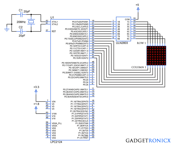
LED's have a wide range of lighting applications in our daily life and surprisingly it also can be used as a display when interconnected together.LED dot matrix is nothing but collection of LED's interconnected together which can be lit by accessing through rows and columns.This dot matrix is used in banks, lifts, buses and much more where displaying of information is necessary.This tutorial demonstrates dot matrix interfacing with arm7 series microcontrollers.
8×8 DOT MATRIX:

|
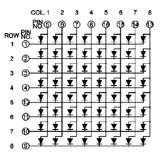
| Common anode LED matrix |
The above diagram shows the connection configuration of 8×8 LED dot matrix where each row and column consists of 8 LED's totally.The above figure shows the common Anode configuration where the LED's are sourced through the columns from the Microcontroller pins and sinked through the rows to the pins.The Switching of the LED's should be faster to form a pattern in the dot matrix display.
ULN2803:
STEPS TO DISPLAY A CHARACTER IN DOT MATRIX:
- Make the pins of each row high one by one, once high signal is applied to the ULN2803 input it will sink the currents of LED in that row.
- Activate column pins for your pattern or character for each rows.
- Use very small delay in the matter of milli seconds between each switching, this will make the dot matrix to display a your desired pattern or character.
TO DISPLAY A HEART SYMBOL IN DOT MATRIX:

|
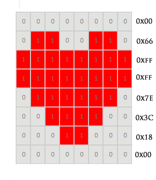
| Heart Symbol display |
This tutorial demonstrates displaying a heart symbol in the LED dot matrix.As you can see in the above diagram the dot matrix consists of 8 rows and columns with a heart drawn over it.The 1 represents the LED's which need to switched ON to display the pattern whereas 0 represents the LED in off state.The respective values for each column of each row activation was given, all you need to do is place the values in array and assign it to the pins of the Controller.
CODE:
This code was built using Keil uVision 4.
#include

             unsigned char row_val[8]={0x01,0x02,0x04,0x08,0x10,0x20,0x40,0x80}!unsigned char col_val[8]={0x00,0x66,0xff,0xff,0x7e,0x3c,0x18,0x00}!void delay(void)!int a!int main(void)  {    PINSEL0=0!PINSEL1=0!IODIR0=0x0000ffff!while(1)    {  for(a=0;a<=7;a++)  {  IOSET0|=(row_val[a]<<0)|(col_val[a]<<8)!delay()!IOCLR0|=(row_val[a]<<0)|(col_val[a]<<8)!}  delay()!}  }    void delay(void)  {  unsigned int i!for(i=0;i<=2000;i++)!}
.


