Everyone loves music and some have the habit of wearing their headphones all the time listening to cool music.For those music fanatics this headphone amplifier circuit will be a great hobby build since it delivers amplified mind blowing music to your ears.
WORKING OF CIRCUIT:
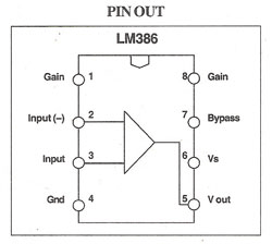
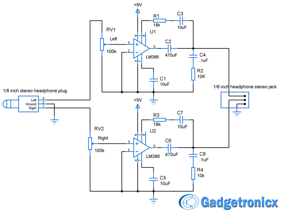
The circuit is built around LM386 amplifier chip which operates at 4 to 12V.This IC is capable of giving output up to 200 and the gain can be adjusted by adding external components to the pins 1,8 and 5 of this LM386 Chip.The above circuit consists of separate amplifier units for right and left channel.Working of only Left amplifier unit is given below since the both units are identical in nature.

In our circuit 1/8 inch headphone plug acts as audio input to the entire circuit.Audio from right and left channel is amplified separately and then the amplified output is given to 1/8 inch output jack.We can connect out headphones from that jack for some mind blowing music.
This LM386 chip consists of series of internal resistors connected between pins 1 ,8 and 5.As i already stated the default gain would be 20.In order to reduce that to R1 along with C3 is added between the pins 1 and 5.This brings the gain value to 11 with great noise reduction in the output.
The RC network using R2 and C4 is added in order to function as a output loading network.This stabilizes the load impedence when high frequency input is encountered and this in turn prevents oscillation.The capacitor C2 acts as a coupling capacitor blocking DC elements from the output audio signal.C1 was added to improve the power supply rejection from the above circuit.
NOTE:
- The circuit can be powered by a 9V rechargeable battery.
- The gain can be altered if you are using a speaker by adding external Resistors between the pins 1 and 8 as narrated in the datasheet.
ATTRIBUTION:Minidisc Headbanger


Hola, el c4 y c8 de .1uF son condensadores ceramicos sin polaridad de 25v?
Hi Jose,
Yes you can use non polarized ones of 25V
How much volt of these capacitor???
Jabir,
25v cap will do good.
R2&R4 resistor is not 10k.It will be 10 Ohms.
hello there.may i ask what the polarity of the 10uF and 470uF capacitors are?i hope you can answer ASAP.thanks
Hi JPC,
For 10uf negative goes to the ground.For 470 uf positive connects to output of LM386