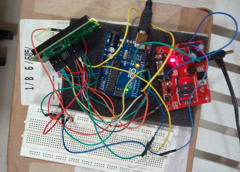
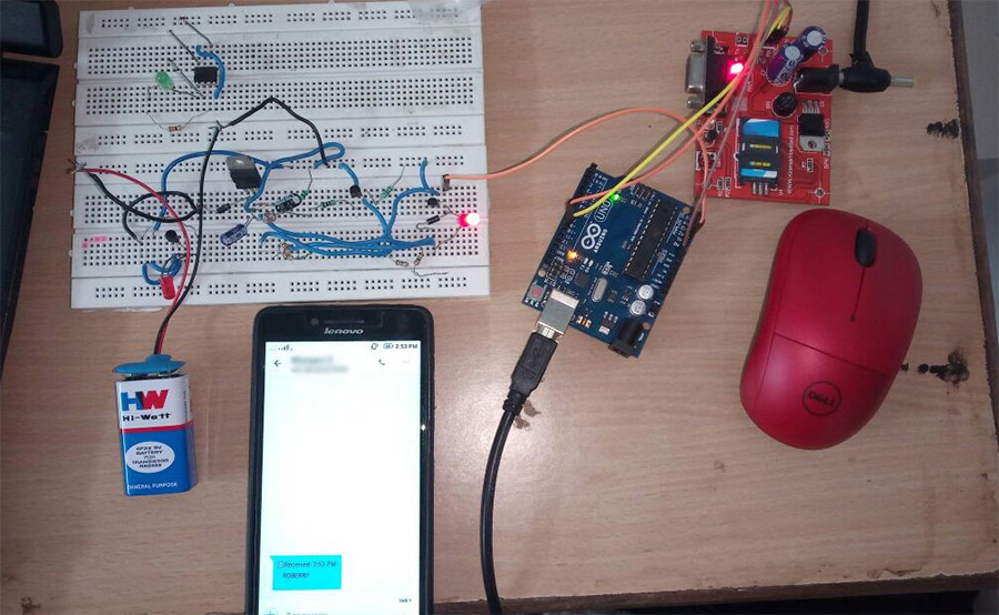
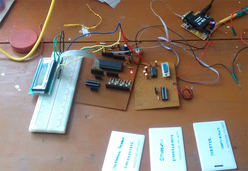
GSM (Global System for Mobile Communication) technology lets user to communicate with others across mobile networks hence it offers a vast area of coverage.Interfacing GSM technology with microcontroller will enable us to extend the communication to cover large area.This tutorial will teach you about interfacing GSM module with atmega32 AVR microcontroller and program it to communicate it with another user.
GSM MODEM:
GSM modem is nothing but a special hardware that modulates and demodulates GSM signals.There are plenty of GSM modems specially designed for interfacing and working with Microcontroller, you can find it online.We are using GSM SIM900A model in this tutorial to explain the interfacing.
PARTS REQUIRED:
We have added "Buy here" links in the below table to buy the listed components with ease.Since we are a sales partner of Amazon you could do a favor by buying parts from below link and this will earn some referral fee for us.By this way you could be a indirect contributor to our site.
NAME |
SPECIFICATION |
NUMBER |
LINK TO BUY |
| GSM/GPRS Modem | SIM900A | 1 | Buy here |
| Microcontroller | AVR | 1 | – |
| LCD | HD44780 | 1 | Buy here |
AT COMMANDS:
These are the set of commands that are predefined in order to establish a communication between controller and modem.Also with the help of these commands a SMS or call has been made out.Take a look at the "Commands used in a GSM modem" for detailed description about it.
DESIGN:
STEPS TO INTERFACE GSM MODEM WITH MICROCONTROLLER:
STEP 1: MODEM TESTING:
The Modem consists of two indicating LED's Green and Red to indicate the availability of the network.Green indicates the availability of the network whereas red indicates its absence.Turn the modem ON and wait for sometime to register itself in GSM network.
STEP 2: INTERFACING WITH AVR MICROCONTROLLER:
The Communication between AVR and modem takes place through USART protocol.GSM Modem SIM900 works on TTL level hence we can interface directly to RXD and TXD pins of AVR microcontroller.There is no need of using Voltage or level converter between them.However if you ever happen to buy a SIM300 or other module which operates above TTL level, you may want to use MAX232 level converter IC to make the communication possible.
STEP 3: INITIALIZING MODEM:
The modem must be Initialized using the commands and then the process you are about to carry out must be selected.In this tutorial am going to initialize the modem and them make it to send a message "Hi Murugan" to my mobile using the GSM modem.And then i will reply to the message which will be displayed in the LCD interfaced to the microcontroller.
CODE:
#include
#define F_CPU 8000000UL #include
#define ctrl PORTB #define en PB2 #define rw PB1 #define rs PB0 void lcd_cmd(unsigned char cmd)!void init_lcd(void)!void usartinit()!void lcd_write(unsigned char data)!unsigned char rxvalue(void)!unsigned char rxdata,a,cmd,b!unsigned int z!unsigned char message[15]!unsigned char cmd1[]={"AT"}!unsigned char cmd2[]={"AT+CMGF=1"}!unsigned char cmd3[]={"AT+CMGS="}!unsigned char cmd4[]={"Hi Murugan"}!unsigned char cmd5[]={"9092*******"}!int main () { DDRC=0xFF!DDRB=0x07!init_lcd()!_delay_ms(50)!usartinit()!lcd_cmd(0x80)!lcd_write(0x47);// G lcd_write(0x53);// S lcd_write(0x4d);// M ///**** GSM send function****/////// for(z=0;cmd1[z]!='';z++) { UDR = cmd1[z]!_delay_ms(100)!} UDR = ('\r')!_delay_ms(500)!for(z=0;cmd2[z]!='';z++) { UDR = cmd2[z]!_delay_ms(100)!} UDR = ('\r')!_delay_ms(500)!for(z=0;cmd3[z]!='';z++) { UDR = cmd3[z]!_delay_ms(100)!} UDR = ('"')!_delay_ms(100)!for(z=0;cmd5[z]!='';z++) { UDR = cmd5[z]!_delay_ms(100)!} UDR = ('"')!_delay_ms(100)!UDR = ('\r')!_delay_ms(500)!for(z=0;cmd4[z]!='';z++) { UDR = cmd4[z]!_delay_ms(100)!} UDR = (26);// ctrlZ-> to send the messge _delay_ms(100)!///**** GSM receive function****/////// while(1) { b=rxvalue()!while (b!='+') // infinite loop when + equal to +.ortherwise untill the loop infinte { b=rxvalue()!} b=rxvalue()!if(b=='C') { b=rxvalue()!if(b=='M') { b=rxvalue()!if(b=='T') { b=rxvalue()!if(b==':') { b=rxvalue()!while (b!=0x0a) // waiting upto next line if no means till loop infinte { b=rxvalue()!} b=rxvalue()!message[0]=b!b=rxvalue()!message[1]=b!b=rxvalue()!message[2]=b!b=rxvalue()!message[3]=b!b=rxvalue()!message[4]=b!b=rxvalue()!message[5]=b!//b=rxvalue()!lcd_cmd(0x80)!for(z=0;z<6;z++) { a=message[z]!lcd_write(a)!// PRINT IN lcd _delay_ms(100)!} } } } } } } void init_lcd (void) { lcd_cmd(0x38)!_delay_ms(1)!lcd_cmd(0x38)!_delay_ms(1)!lcd_cmd(0x38)!_delay_ms(1)!lcd_cmd(0x38)!_delay_ms(1)!lcd_cmd(0x06)!_delay_ms(1)!lcd_cmd(0x0c)!_delay_ms(1)!lcd_cmd(0x01)!_delay_ms(1)!lcd_cmd(0x02)!_delay_ms(1)!return!} void lcd_cmd(unsigned char cmd) { PORTA=cmd!ctrl=(0
NOTE:
- You may want to add up MAX232 IC if your modem output is above TTL logic level.
- You also want to alter the commands fed to modem based on your requirements.


can you please give me working gsm code for atmega 16 microcontroller for avr studio
Harshit,
Code is given in the article, go ahead and use it
hi,
i have a sim900 module
i have a sensor inner my micro (atmega32a)
i want when sensor sense,gsm send a message
how can i connect the gsm whit atmega32a
and how can i program them
tanks
Spehr,
金宝搏188beat网登录appThis article will be your guide, read and follow it
Thank you for this explicit explanation.But then I would appreciate if you can explain further what "rxvalue()" does.Thank you
Hello!!
I have interfaced Atmega 32 with Sim900 GSM module, and I am able to read the message correctly if it is present.But if the message is not present in the particular index and if I am trying to access that message than instead of showing me the no msg present as per the code written below..it just goes in infinte loop.Please if u can help me out in this thing then I would me able to complete the project left.
Code for reading the deleted msg and showing it as an empty msg:
void read_del_msg()
{
char a[16],b[16],details[100],msg[32],n[50];
unsigned int i=1000;
lcd_clear();
uart_init();
printf("AT+CMGR=1\r\n");
gets(a,16);//Stores the first 16 char of SMS
gets(b,16);//Stores next 16 char of SMS
gets(details,100);//Stores next 100 char of SMS
i=strlen(details);
lcd_clear();
goto_p(0,0);
dsp_int(i);
delay_ms(2000);
if(i<10)
{
lcd_clear();
strcpy(n,"No new SMS");
dsp_s(n);
delay_ms(1000);
lcd_clear();
}
return;
}
hi there.i am last year university student and i have to complete a major project to take my evidence of study so i wanna you help me.would you please send to my email address a code(preferly code vision or bascom) that i can read GSM sim900a by ATMEGA microcontroller ?thanks a lot.
email address:mirzaiimehran@yahoo.com
code language c or c++
the code language is c or c++
c language,…
Murugan, can you write and share with us the same C program when the same gsm module is interfaced with an ARM SAM3A4C micro controller instead of an Atmega32 AVR microcontroller to do the same purpose of sending an receiving SMS text through AT COMMANDS.thanks,
this code is not working in atmel studio..what should i do
check your code once again , and which compiler version you are using?program is correct
the code is working perfectly with some corrections in for loop and in the 169 line.
what is the correction in 169th line?and the fuse bits settings?
The code is nice and simple to understand…but i wonder have you tested it?
Because i am going to use it.
I am making a project on GSM
yeah its tested and working fine..goahead…………
FYI Seems like there are several error created in transcribing the code to the web page.2 include statements with no arguments, cmd 1 rather than cmd1 , etc.etc.
Rando,
Sorry for the error and thank you for pointing it out.Now the article is updated.
Can u give me updated AVR code on my email idpreciousviral@gmail.com?
1 luv u