|
| Click over the image to view enlarged one |
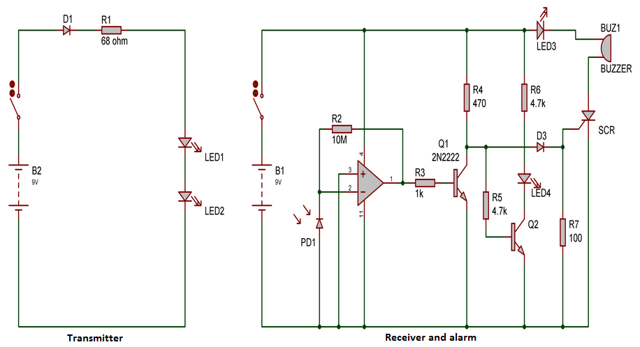
Burglar Alarm circuit can be seen wide over the internet and some of them are real simple to implement to do it self on our home.Each circuit needs different kind of trigger for activation of the alarm, some uses trip wire while other uses shadow detection, light interruption and other techniques.Here is a similar circuit which uses Infra red beam to detect the intrusion into any place and trigger the alarm attached with it.Here the circuit can be split into two types a transmitter part which used to generate Infra red beam while other is a receiver and alarm circuit used for to indicating intrusion.
Working burglar alarm Circuit:
The transmitter module of the above circuit generates current drive for the Infra Red light Emitting diode LED1 and LED2.In the transmitter the current through the LED1 and LED2 was controller by resistance R1.The IR beam generated by these two LED's should be aligned to make it fall on the PD1 Photo diode which was used to sense the IR beam in the receiver.Therefore any interruption in the beam will be sensed instantaneously by the receiver circuit.
Photo Diode PD1 was the important component in the receiver part which converts the incident light beam into current.The photo diode was paired with a current to voltage converter using a Op Amp LM324 which was used to convert the induced current into equivalent voltage at the output. This Voltage was used to switch the Transistor Q1 ON which keeps the collector of the Q1 at ground potential and this in turn keeps the transistor Q2 and SCR in the off state.To summarize, when the infra red beam is undisturbed the transistor Q1 will be in the ON state while the Transistor Q2 and SCR will be in the OFF state thus there will be no alarm.
When the beam was disturbed the transistor T1 goes to cut off mode due to the absence of induced current in the Photo Diode.This makes the transistor T2 to conduct and therefore LED4 glows indicating intrusion and SCR fires enabling the buzzer to produce the alarm sound.The SCR stays ON if once fired even if the gate drive is removed by retrieving the beam back on the photo diode.Therefore the microbuzzer continues sounding the alarm and LED3 continues to glow after the beam interruption .Switch S2 needs to be opened momentarily to reset the system and get it ready to detect the next intrusion.The status of the LED4 can be used to set up the beam alignment while initializing the system to detect intrusion.When the beam was not aligned properly the LED4 will glow and extinguishes if you make the right alignment for the path of IR beam.


WE ARE USING LEDs IN THE CIRCUIT WHAT TYPE OF LEDs ARE BEING USED?ARE ALL LEDs ARE IR?
Muhammad,
The LED's used in the transmitter part are IR one's rest usual.