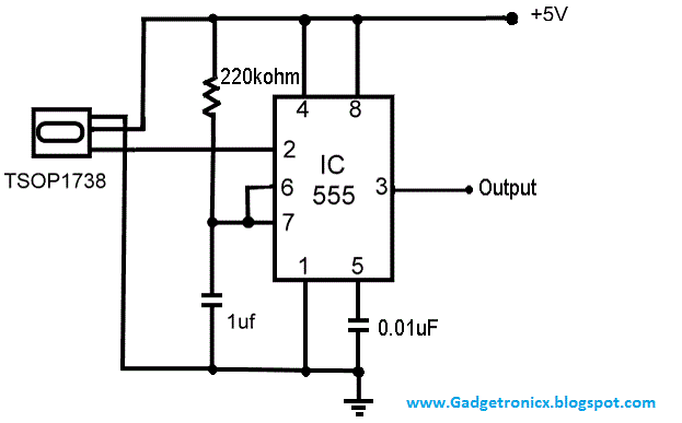
The Infra Red signals are widely used in wide range of remote control applications so it is worthy to know about the transmission and receiving the IR signals.Here the above circuit was a simple Infrared receiver circuit constructed using IC 555 and TSOP1738.The TSOP1738 was nothing but a simple IR detector used widely and here it was used for the same detecting purpose and then the signal was fed into the IC 555 which was wired as monostable multivibrator.Lets move in to the working of the above circuit.
WORKING OF INFRARED RECEIVER CIRCUIT:
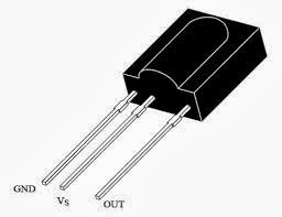
In this above circuit the TSOP1738 forms the main constituent of this circuit and this was designed to detect the IR signals from any source.This was used to detect the signals of the range of 38 KHz and thus named as "TSOP1738" and last two numbers of each of this TSOP series was named for their receiving frequency range.The pin configuration was given below.
The Vs was connected to 5v power supply and the GND to ground respectively.And the output was taken from the OUT pin.The TSOP gives high signal as output in the absence of detection of any IR signals and low output whenever IR signals incident on TSOP1738.This logic was used in the above receiver circuit to to detect the Infra red signals.
Since the IC 555 was wired as monostable multivibrator the negative trigger to the pin 2 of the 555 IC will result in a high output at the 3 pin of the IC 555 thus indicating that the detection of Infra Red signals.But in the absence of IR signals the TSOP will give a high positive trigger thus there will be no output obtained from the 3rd pin of the IC 555.By this way the receiver circuit using TSOP1738 and IC 555 works.


will it constant output
Hi,
What you mean constant output.The output of 555 changes with the IR beam incident on TSOP.
ok, i will try that tyhen and let u know the outcome.Thanks again
thanks for the suggestion but i am not sure what that means exactly.I would prefer more details or even a schematic for your suggestion.However, in the meantime i am going to try what i think u r saying.BTW i am not a pro at electronics i only try to follow the schematics of circuits i am interested in(cause i love to make things and see them work), but i have little to no understanding how they work.
i made this circuit using a ir receiver from a toy helicopter.It works for the most part, but there are times when the buzzer keeps going off without being triggered by remote.Any idea as to why this is taking place and how i can solve it?
Ced,
Try adding a pull up resistor to the output pin of the TSOP sensor.It may help to keep the circuit in a fixed state and triggers only if IR beam is incident on it.
Ced,
Nothing complex add, a 10K resistor from 2nd pin of the IC 555 to the Vcc +5v
hello,
i am trying to convert IR-RF-IR for a long range IR remote control without using microcontroller, is that possible?could you please help me in this?
Thanks!!
Jenno,
Can you provide a bit elaborate explanation on what you are trying to do?
Hello!
Could you please tell me what is the max voltage of the 1 microfarad capacitor and the other capacitor?Will it not be possible that the voltage from the capacitor will flow backward to the TSOP's output pin and cause damage?
I just need some clarifications on those issues.
Thanks!
Foobar,
Output of TSOP1738 is not tied with the Capacitor, it feeds the pin 2 of the Timer IC 555.
Oh, I see.May I know what's the max voltage of the 1 microfarad capacitor and the other capacitor too?
Thanks!
can i use it to flash an led in the same frequency as the remote transmits
Henning,
The above circuit will give logic high when IR is incident on the sensor , it will not give out frequency output.However you can do it by wiring the 555 as astable multivibrator.
Good day!does this circuit function as toggle switch?
meaning, the second time it detects IR signal, the output will turn low.
No it wont work that way Aaron it was just a combination of IR sensor TSOP and monostable multivibrator.Whenever there is a negative trigger the output will be high…You cant use it as a toggle switch but here is a circuit which might work as you expectedRemote control of electrical appliancesThe receiver part of the above project might help your cause
Good to hear this.Keep visiting us
Thanks.This helped with the keyesIR proximity switch!
Glad to hear it Cheers.