|
| LED driver circuit using MP3302 |
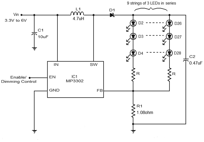
LED Circuits have been quite fascinating to the hobbyists and are very well known for their attraction.LED's grabbed a significant position in the lightning since it consumes low power and also provides a great look to it.So here is a LED driver circuit diagram which employs IC MP3302 , a specially made step up converter designed for driving array of white LED's from a single lithium battery.This circuit will be very helpful to design and implement your own lighting circuit using a small power source.
WORKING OF LED DRIVER CIRCUIT DIAGRAM:
The input voltage ranges from 3.3v to 6v was fed to the IN pin of the IC MP3302 through the input bypass capacitor C1.A inductor of range 4.7uH was used to improve the efficiency and it was connected to the pin SW which is the power switch output of the IC.Resistor R1 is employed as the feedback resistor and it helps to control the LED current.The resistors named as R is current limiting the current through the LED thereby it will be useful to adjust the brightness of the LED's.

|
| Resistance value table |
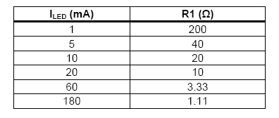
The above table illustrates the selection of the feedback resistor R1 for the given LED current.The IC MP3302 also provides room for dimming of the IC's connected to it.It can be achieved by providing the PWM signal ranges from 200Hz to 1KHz to the Enable/dimming control pin.The minimum recommended amplitude of the PWM signal should be 1.5v for controlling the brightness of the LED's.The bottom of the LED string should be connected to the pin FB (Feedback Input) and the IC will regulate the voltage across the current sense resistor between FB and GND.
The circuit also uses a Schottky diode MBR0520 which has the characteristics of fast recovery and low forward voltage.This circuit is capable of drive 3 parallel strings of 9 white LEDs in the series and a total of 27 LED's can be lighten up through this IC MP3302.A capacitor C2 was connected along the string of LED's and was used as a output bypass capacitor.


