|
| Mains operated LED lighting |
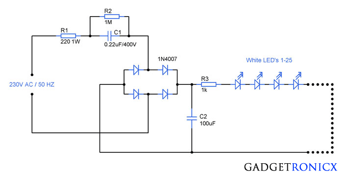
LED's holds unique place in lighting due to its miniature size and its low power consumption.No wonder it was considered as future of lighting.But in order to built a led lighting circuit we need to built special power supplies with regulators, transformers and this might make them hard to construct.As a solution the above circuit demonstrates construction of mains operated led light circuit which derives power directly from the mains supply without usage of transformers.
WORKING OF MAINS OPERATED LED LIGHT CIRCUIT :
The household AC power supply of 230V is used to power this entire circuit.Here high volt AC is fed as input and it is stepped down (high volt AC to low volt AC) using Capacitive reactance.When a AC supply which continuously reverses its polarity is connected with a Capacitor, the plates of the capacitor continuously charging and discharging and the related currents always flows in and out of the plates and this induces a reactance to oppose the flow.
The Reactance produced by the capacitor depends on the frequency of the input signal.Adding R2 is very necessary since it will bleed the stored current from the capacitor when the entire circuit is switched off.It is capable of storing up to 400V and in that case if you failed to add resistor it will deliver a lethal shock even though the circuit is switched off.Additionally Resistor R1 is also added to limit the current flow.
The next stage of the Circuit is the bridge rectifier which is meant to convert the AC signal to DC.The capacitor C2 serves the purpose of removing the ripples in the rectified DC signal from the recitifier.The resistor R3 serves as a current limiter for all the LED's we are about to use here.
Here we have used white LED's in the Circuit which possess a voltage drop of about 3.5V and consumes 30mA of current.Since we have connected LED's in series the consumption of current is very less.Therefore this circuit proves to be a efficient in power consumption as well as on cost basis.


Dangerous circuit: When one of the LEDs in serie breaks down, the voltage over C2 will increase to 325V!
sir in this circuit i am trying in my home but after some time the R1 resistor burn out plz tell me the reason
Venky,
Do check the Wattage rating of the resistor you are using.Mismatched components can lead to catastrophic failure, so use high wattage resistors and capacitors with high voltage rating.