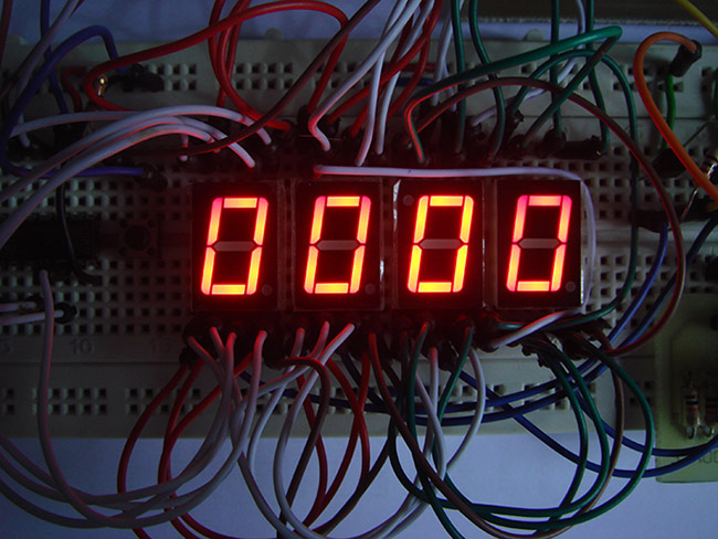
People / Object counter circuit have a wide variety of applications in Banks, Hospitals, factories etc.This project focuses on building an effective counter using IR as a sensing element and capable of counting from 0 to 999.This project uses Two simple IC's ( IC 555 & IC 4026 ) with IR transmitter and Receiver to detect the incoming people/object.
This Project comprises of Three parts
IR TRANSMITTER:
Freq = 1.45 / ( R3 + 2R1 ) C2IR transmitter was wired around Astable multivibrator using IC 555.As we all know that multivibrator produce square wave pulses and we gotta fix the frequency of the output signal as 38 Khz since we are about to use TSOP 1738 an Infra red sensor which is capable of detecting signals of 38 Khz.The frequency of the astable depends on R1,R3 and C2.So lets do some math
= 1.45 / (470 + 2 * 1690 ) * 100 * 10
=37.6 Khz
So we have fixed the IR frequency of 38 Khz and now Transmitter part is done.
Please note that i have used a simple IR transceiver module (brown board – right top) for this project to make things simple.You can use use IR module like i did if you have any.If not build the IR transmitter using IC 555 as shown in above circuit.The receiver part was given in the below circuit diagram.
IR RECEIVER AND 7 SEGMENT DRIVER:
 The sensed output was fed into trigger input of the monostable multivibrator using IC 555.As we all know that Multivibrators gives high output when low signal as fed into its trigger and low output when high signal is fed.Two multivibrators was cascaded to prevent multiple increments in the counter since using a single multivibrator changes the output with every low to high or high to low transition in trigger pin.The above circuit diagram comprises of both Infra Red Receiver as well as 7 segment driver.The IR signal is sensed by TSOP 1738 which is capable of sensing the IR signals of 38 Khz frequency.This TSOP will give high signal as output when IR signal is sensed and low signal when IR falls on it.The third pin of the TSOP gives the output and its fed into next stage of the circuit.

|
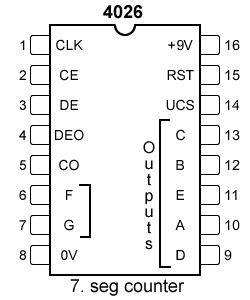
| IC 4026 |
Next stage of the circuit is 7 segment drivers which is done by three IC 4026 which is a 7 segment display decade counter.This IC is capable of incrementing the digits in 7 segment with clock input in the CLK pin.The output from the monostable multivibrator forms the clock source for this IC 4026.Read more about7 Segment interface with IC 4026.
WORKING:
The transmitter and Receiver was initially aligned and this makes the TSOP 1738 to give low signal to the multivibrator which in turn gives high at the output and this forces the 2nd Multivibrator to give low signal to the CLK pin of the right most IC 4026.When the IR beam in interrupted the TSOP gives high output which in turn makes the Multivibrator 1 to give low signal trigger to the 2nd multivibrator.
The low signal input pushes the output of Multivibrator 2 to high state thereby a successful transition occurs and this forms a single clock pulse input to the IC 4026.Thus this makes the IC to increment a single value in the 7 segment.Now cascading three segments will enable us to display count up to 999 which was done by connecting the CO (Clock Out) pin of the IC 4026 to the input clock pin of the preceding IC 4026.
Whenever IC 4026 finishes counting from 0 to 10 it gives out a logic transition in its CO pin which sources the clock for preceding IC at CLK pin which in turn increments the value by 1.By this way three IC's work together to display digits from 000 to 999.
WORKING VIDEO:
NOTE:
- You can increase the count value by adding 7 segments along with IC 4026 by connecting the CO pin output of the Preceding IC to its CLK pin.
- You must use two multivibrator or else you will obtain two increments for a single incoming person/object.


I have followed the schematic explicitly, and put together both the transmitter and receiver, but it does not register a count.I also have tried an IR module with the output pin connected to pin 2 on the 555, but still not working.
sir can you use IR module in this circuit?where can i connect the output pin and the vcc?
Hi……please add the video of connection .I know that its hard but really its very difficult to do connections
Hi Jay,
Kindly follow the circuit diagram, it should help you with the connections.188bet服务官网Unfortunately our team is stuck up with other projects and we are unable to create a video for this
Sir how we can change this project.mean if the object passing through one way is increase and if we want to reverse the object so that the 7 segment display show decreamented value(reversing the objects )
Hi Frank if I'm gonna use the IR transmitter module where should I connect it in the 555?
Use it in the Output pin 3 of IC 555
Why did u need 2 555 timer in the ir receiver circuit,, is it not possible to use 1 timer, connect the input of that 1 timer to the tsop1738 then the output of that timer will be directly connected to counter.is that possible?
Just a quick question, your schematic does not show any current limiting resistors between the 4026 and the 7 segment LED, but I see them in your video.I'm assuming they should be in the schematic as well?any ideas as to value of these resistors?Thanks
Hi Dave,
Yes resistors must be used for this project.Use 470ohm for this circuit.
Hi sir,
Ur work is amazing if you don't mind would I be able to get the codes?It will be really a big help for me from u.I need the codes to continue with the project.
Could you kindly please send it to my email:begum786@hotmail.sg
Regards,
Zaana
Ebramshah,
What code you are referring to?
The codes for the circuit to work sir after we connect we need to upload the codes to the board right.I am referring to them
Ebramshah,
This whole circuit is made of digital IC chips and now programming was involved in this circuit.
Hi sir it would be really a great help if you could send the codes to my email(begum786@hotmail.sg).Please I really need your help.Thank you very much!
sir can i get full circuit build video please?
if you have?
please send to my mail
Hi Manjunath,
Unfortunately i don't have that circuit building video.The circuit may seems to big but once you get started it will be easier to implement on the bread board.Give a try
sir wld i be able to get the codes?
Hello boss your using only two 555 ic where is another one?
Many of us getting confuse in connection of transmitter to receiver unit .like where we have to connect ir module.
Manjunath,
I have used IR module in my project, it consists of both transmitter and receiver part in it.Note that brown color board in the picture that was my IR module.You can use this kind of module if you have one.Or you can build one like i have shown in the circuit diagram.