Remote control of home appliances has been a common thing as we use appliances such as TV, Air Conditioner etc in our daily life.This electronic project intended to demonstrate a simple concept of remotely controlling the switch ON and switch OFF operation of the AC mains operated electrical appliances. This project uses Infra Red to establish communication between the remote and the electrical appliance intended to be switched.This project comprises of two parts a transmitter and receiver which makes the control of home appliances possible.
INFRA RED TRANSMITTER:
The transmitter circuit is nothing but an astable Multivibrator circuit built around timer IC 555 which produces a continuous square wave pulses.The output of the NE555 is amplified using a PNP transistor transistor to drive the IR LED's to emit the IR beam.The output timer feeds the IR LED's used here is same as the one typically used in TV remotes which are easily available and also costs low The circuit operates from 9v battery which can be connected to the circuit through switch SW1.
RECEIVER SECTION:

|
| Click the image for enlarged view |
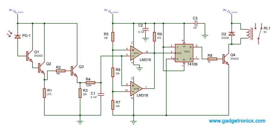
The input part of the circuit comprising of photodiode PD1, Darlington Connection made with transistors Q1 and Q2 and resistor R2 constitute the current to voltage converter which converts the photocurrent generated by the photodiode into an equivalent voltage in fact the photodiode and darlington connection together make a photo-darlington.The darlington connection amplifies the photo current generated by the photodiode thus allowing even a feeble IR power to be detected.The equivalent photo voltage appears across R1 and So across R1 we get a replica of what we produce at timer IC output in terms of wave shape but not in amplitude would vary with distance and other factors such as angle of arrival of the IR beam at the sensor and so on.

|
| LM319 Pin diagram Attribution: www.datasheetdir.com |
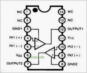
Transistor Q3 is wired as a non-inverting switch.The low pass filter constituted by the Resistor R4 and Capacitor C1 produces a DC value of approximately 3 volts.The DC voltage feeds the junction of inverting input of IC1:A and non inverting input of IC1:B.The two extremes of the window comparator circuit are decided by the two reference voltages appearing at the inverting input of IC1:B and non inverting input of IC1:A which is 2 and 4 volts.This window comparator is configured that whenever the input voltage lies within the window of 2 to 4 volts, the output goes to high state.If the input voltage is less than equal to 2 volts or more than equal to 4 volts, the output goes to low state

|
| IC 74109 Pin diagram |
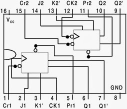
The output of the window comparator feeds the clock input of the J-K flip flop which is wired as a toggle flip flop.The output of a toggle flip flop toggles i.e goes to High state if initially in LOW state and to low state if initially high, every time it is clocked.Output of flip flop feeds the transistor Q4 base terminal.Q4 is wired as switch relay coil as its collector load.The relay operates and its normally open contact closes every time the transistor is switched ON.
Initially with no IR light falling on the sensor the DC voltage appearing at the input of the window comparator is near zero.The input of the window comparator is near zero.The comparator output is in low state with the result that transistor Q4 is in OFF state and the relay remains inactivated.When the IR light is made to fall on the sensor for a short period of time, a positive going pulse with amplitude of about 3 volts appears at the input of the window comparator.The output of the comparator goes high state which in turn switches the transistor Q4 On Relay RL 1 in turn gets activated and its normally open contact closes thus the switching ON the intended gadget or appliance.
NOTE:
|
The above electronic project is intended to switch the electrical appliance connected to it and not controlling its operations.Remote control gadgets are built around dedicated chips with embedded technology meant for performing a specified function.
|


Mr Donald,How to interface With microcontrolers and have separate output per each button?
Ebrahim,
You might need an encoder at the button input.Then decode it in the receiver end using the Microcontroller.That's one option you can try it out
Good One
Thanks…Try this ,its sure you will love it
nice project