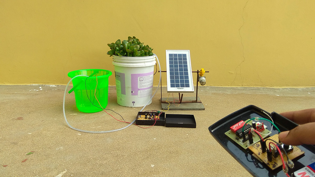
Beacons are used for the purpose of guiding travelers or marking significant places or things.In early days fire and light serves as beacon for travelers as explorers.Nowadays beacon have evolved very much from fire and light.金宝搏188beat网登录appWhile on a trek i have noticed officials have installed a simple sound alarms as beacons at certain spots to guide trekkers.I thought it was a nice idea and would be better if it was powered by Solar power hence built this Solar powered beacon project.
金宝搏188beat网登录appOn seeing this we have also used similar beacons in treasure hunt game in my college campus, where the sound guides players to a treasure.Hope you will find similar application for this circuit.
GENERAL APPLICATIONS OF BEACONS:
- Navigation
- Guidance purposes
- Vehicles
- Communication
SOLAR POWERED BEACON WITHOUT BATTERY BACKUP:
In this circuit the power is directly derived from the solar panel.So this circuit will not work in night or in the absence of sun (cloudy condition).So i advice you to see if your application can tolerate this drawback.
The circuit is powered by a 12v solar panel.It is capable of delivering 11.8v to load under optimum sunlight and 11.4v when sunlight is less intense.A electrolytic capacitor C1 was used to stabilize the voltage output from the solar panel.Use a diode D1 to prevent the reverse flow of current to panel from Capacitor C1.Considering the voltage drop 0.7v of the diode, the finally voltage output from panel will be around 10.7v.This Voltage is sufficient for our siren circuit.
WORKING EXPLANATION:
Op Amp works as astable multivibrator generate square wave.This in turn drives the buzzer.Thus this forms the alarm part of our circuit.After the circuit is powered ON output of Opamp is unpredictable.Let us assume that the output is Low, logic ‘1'.The output is fed back to the Non-inverting input of opamp through the voltage divider R2 and R3.Here the input voltage to + terminal of opamp will be half the supply voltage.
When the output logic is 1 the capacitor C1 starts charging through feedback resistor R1.When voltage in the capacitor exceeds non inverting terminal voltage output switches to logic 0.This makes the capacitor to discharge via R1.
When output goes low, nil voltage will appears across the Non inverting terminal of Opamp.As a result when capacitor fully discharges and the point where no voltage appears across C1, the opamp switches its state to 1 again.This cycle repeats and gives a square wave as output.
F = 1 / R1C1
This gives us a frequency of 20Hz as output from our circuit.
BREADBOARD ASSEMBLY:

NOTE:
- Clouds, less sunlight and other external factors may interrupt the circuit operation.
- Circuit will be functional only during daytime.
- Optional Cap C2 is to steady the input voltage level.
SOLAR POWERED BEACON WITH BATTERY BACKUP:
You can use this circuit if you cannot tolerate the failure of this beacon in night and cloudy condition.Choice of battery is very much important for this circuit.I would suggest you to use 8v Lead acid battery for this purpose.
CHARGING BATTERY:
Most of the 8V Lead acid batteries need to be charged at around 9.4v for reaching its maximum charge capacity.Also supply current should be around 20% of it's battery rated current.Therefore considering our battery 1Ah, 20% – 200mA is sufficient for charging.Solar panel here i used is capable of delivering that current so it wouldn't be a problem.As i said earlier the panel will deliver 10.7v even under non optimum conditions so am gonna consider that for calculation.
To regulate the voltage applied to the battery am gonna use a simple zener diode which will provide constant current charge to the battery under fixed voltage.Zener diode BZX79-C10 rated 9.4v.So to determine R4
R = (Vin – Vz ) / ( Iz + IBat)
R = 10.7 – 9.4 / ( 50mA + 200mA )
R = 100 ohms (approximation to standard resistor value)
So this setup will safe charge 8v Lead acid battery via Solar panel.
DISCHARGE OF BATTERY:
Coming to the discharge part of our battery.Now let's see how much current our beacon actually consumes
I = IBuzzer + IR (Current through voltage divider R3 and R2 at 50% duty cycle)
I = 15mA (from datasheet) + 10.7 / 2K @50%
I = 15mA + 2.67mA
I =17.6mA.
But let's consider 30mA as current drawn from the battery, just to be a safe assumption.So this circuit will take 30mA which gives 30mAh when used for an hour.So this battery can pretty much power the circuit for about 25 hours still leaving 25% of charge in the battery.
This is pretty much in theory but in real time not everything goes as per your math.You cannot expect sunlight throughout the day of usage.So best guess is that you can run your beacon for around 20 hours in real time before charging even though your math gives 25 hours before depleting the charge to 25%.Also it is a good practice to use Lead acid battery only up to 75% of charge for extended battery life.
Also it is always good to know the charge level of your battery.金宝搏188beat网登录appHere is a guide to build your ownLead acid battery charge indicator circuit.The rest of the circuit is identical to the circuit without battery backup.Refer to that explanation.
NOTE:
- Always do your math considering the uncertainty of atmospheric conditions that affects solar power.
- Go through your battery datasheet thoroughly to understand your battery specifications, it might vary.
- The cap C2 is to steady the output voltage from the solar panel.
Hope this solar beacon will be helpful to you.Please post your thoughts, feedback and queries about this project below in the comment box and I will be glad to help you


