|
| Stepper Motor Controller |
Stepper motor is a brushless DC motor which divides a single rotation into number of equal steps.These types of motors are widely used in robotics and other applications where precise movement plays a crucial role.This Circuit tutorial demonstrates building and working of Stepper motor controller using IC 4070 and IC 4013.
WORKING OF STEPPER MOTOR CONTROLLER CIRCUIT:
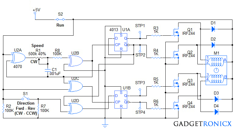
Referring to the schematic diagram, two IC's U1A,B and U2A,B,C,D form the oscillator, and forward-reverse quadrature signals needed to drive the stepper motor M1.Specifically, XOR gate U2A, wired as an inverter, and U2B wired as a buffer, form an oscillator circuit with R1, C1 and R8.Resistor R8 serves to protect the input of U2B from excessive over voltage and current.C1 and R1 determine the frequency of the oscillator.As R1 is reduced (turned CW) the frequency increases, the stepping rate increases as well.If a slower stepping rate is desired, the value of C1 can be increased as needed.
U2B is connected to dual flip-flop, U1A clock input and to U2C.U2C, is wired as an inverter to provide an inverted clock to U1B.The Qnot output of U1A is connected to the data input of U1A.Thus, when each rising edge of the clock is seen by U1A, the output status of Q and Qnot of U1A are toggled (reversed).
Switch S1, is connected to R7 and the input of XOR gate, U2D.When S1 is pressed, U2D works as an inverter.When S1 is open, U2D works as a buffer.The Qnot output of U1A is connected to the other input of U2D.The output of U2D is connected to the data input of U1B.Since the clock input to U1B is the compliment to the clock input to U1A, the outputs of U1B will update on the opposite edges of the U2A,B,C clock.Since U2D inverts or just buffers the Qnot output of U1A.The outputs of U1B will either lead or lag the outputs of U1A by 90 degrees, producing the desired quadrature output.
The rest of the circuit is straightforward.R3-6 supply current to the driver transistors, Q1-4.They are shown as IRFZ44, n-channel MOSFETS, but any n-channel MOSFETS, or BJT (NPN) transistors can be used provided the have sufficient gain and current ratings for the stepper motor used.D1-4 provide fly-back protection for the drivers to discharge the magnetic field energy in the stepper motor coils.
NOTE:
- Switch S2 is the Stop-Run switch to provide power to the circuit.
- Pressing S1 reverses the direction of the stepper motor.
- If higher voltages are required (above 12V), a 7812 regulator can be inserted to power the U1A,B and U2A,B,C,D portion of the circuit.


