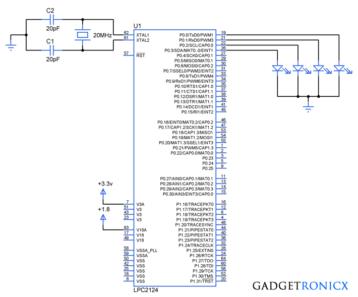
Timers are one of the important concepts in a Microcontroller since it helps us to create precise time delays for a specific application.The usage of timers are inevitable in many of the Embedded Applications which we use in our real life.This tutorial focuses in creating time delays using timer in ARM7 (LPC2124) Microcontroller.
REGISTERS USED IN TIMERS:
I assume that you all are familiar with the Timer concepts in other Microcontrollers such as 8051 or PIC or AVR so i don't need to explain the basic working principle behind the timers.In ARM Microcontroller there are two 32 bit Timers Timer0 and Timer1 which serves the purpose of generating time delays.Here are the registers used to program Timers in LPC2124 Microcontroller.
T0TCR:This register is used to control the functions of the Timer0.Enable and reset operations of the Timer0 register can be controlled by this register.
T0PR:This is a 32 bit Prescale register which holds the maximum value which the Prescale counter can take.
T0PC:This is a 32 bit Prescale counter which specifies the division value of the processor clock before feeding it to the timers.The value in the register increments with every input pulse or Processor clock fed into it.Prescale register T0PR gives the max value this T0PC register can take.When reaching the max count T0PC register gets reset on the next Processor clock.
T0TC:A 32 bit timer counter is incremented whenever Prescale counter T0PC value reaches its maximum level given in the Prescale register T0PR.
T0MR0:These register stores the value which should be compared to the T0TC register.Operations specified based on the T0MCR will be performed whenever a match encounters.
T0MCR:The Match control register is used to specify the operation whenever a match occurs between the value stored in T0MR0 and T0TC register.
T0IR:Interrupt register which consists bits for match and capture interrupts.Writing will reset the interrupts in this register.
Refer the manual for brief description of these registers.You can download the manual from the below link
HOW TIMER IN ARM7 CONTROLLER WORKS:
Like other Microcontrollers ARM controllers count the clock pulses in their timer operation but in a complicated way.Generally the clock fed to the controller is called as Processor Clock (PCLK) at rate which processor works.And for peripherals we can split the value in to divisions by using VPBDIV register to fit our requirements.By default Peripheral clock is equal to PCLK/4 and the same division is used in our code.
- Initially the value in the T0PC increases with every incoming pulse and can attain a max limit up to the value stored in the T0PR register.
- Once the T0PC reaches maximum value it gives rise to an increment of value in the T0TC register.
- The value in the T0MR0 and T0TC will be checked by the processor to detect any match between.
- Then finally interrupt or any operation will take place based on the T0MCR register.
CALCULATION OF TIME DELAY:
Peripheral Frequency = Oscillator Frequecny / VPB divider
Since we are using Default 1/4 divider here our peripheral frequency will be
Peripheral Frequency = 20 MHz / 4 = 5MHz
Then we have to calculate T0MR0 (count) value to generate required delay by matching
Count = (5MHz * Required time delay) – 1
= (5,000,000 * 100ms) – 1
= (5,000,000 * .1) -1
= 4,99,999
Now count 499999 gives the T0MR0 value to generate 100ms delay.So to make it as one sec we have to multiply it with 10.And that we can use it in the Prescale register T0PR, thus we can generate a delay of 1 sec using this.
STEPS TO PROGRAM TIMERS:
- Reset timer0 initially to deactivate counting.
- Load calculated values in the Prescaler register T0PR and Match register T0MR0.
- Initialize T0PC and T0TC registers.
- Select operations using match registers when match is encountered.
- Start the Timer by enabling it through T0TCR register.
- Wait till the interrupt and then clear the flag by writing T0IR register.
CODE:
#include

            void delay(void)!int main(void)  {   PINSEL0=0!IODIR0=0x00000007!while(1)     {     IOSET0=0x00000007!delay()!IOCLR0=0x00000007!delay()!}  }    void delay(void)  {     T0TCR=(1<<1)!//Reset Timer0     T0MR0=499999!//Loading match register value     T0PR=10!//Loading Prescalar register value     T0PC=T0TC=0!T0MCR=(1<<0)|(1<<2)!//Generates interrupt and reset on match     T0TCR=(1<<0)!//Starting Timer     while(!(T0IR&(1<<0)))!//Waiting for interrupt     T0IR=(1<<0)!//Clearing interrupt  }
NOTE:
- You can increase time delay by altering the value in the T0PR register based on the given calculation.


sir, during counting if power failure occurs for few seconds what happened to the counting,..is it restarts or start from the count where it is during power failure..
Sushma,
It will restart the count
what is the max delay that we get using timers in lpc2148