Ultrasonic waves are defined as the sound waves whose frequency is greater than 20Khz and it is not audible to the normal human ears.This ultrasonic possess wide variety of applications from industries (to detect flaws in machineries ) to medicine(for treating and detecting ailments).In fact some animals like Bats, dolphin etc uses these waves to interact with the external environment.This circuit demonstrate constructing a simple 40KHz ultrasonic transmitter built around timer ic 555.
WORKING OF ULTRASONIC TRANSMITTER CIRCUIT:
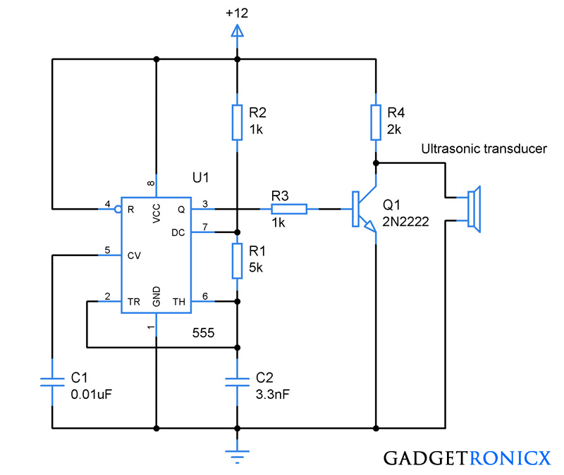
The IC 555 was wired to work as an astable multivibrator which forms the oscillator part of the above circuit.This IC U1 was configured to produce a continuous serial square wave pulses of 40KHZ.And the output frequency was governed by the equation F= 1..44/((R2+2R1)C2) .In the above circuit the components R1,R2 and C2 was selected to give 40KHZ square wave as output.
ULTRASONIC TRANSDUCER:
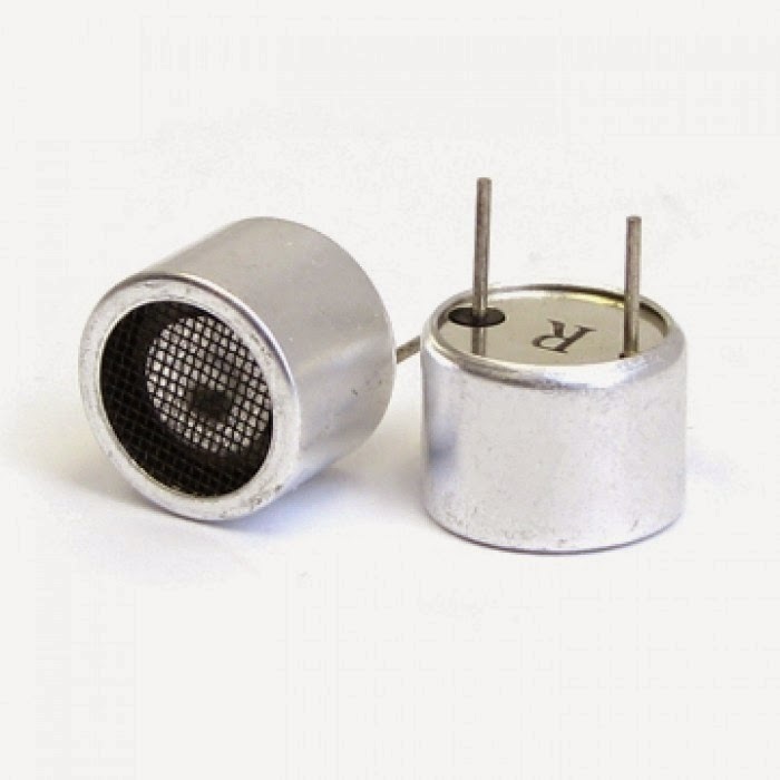
This is the main component of the above circuit which is responsible for converting the input pulse to Ultrasonic waves of equivalent frequency.Usually it was made up of Piezoelectric crystals which have the property of changing size when voltage is applied.Apply input signal will cause them to oscillate and in turn produces high frequency sound waves.Also some components adapt other methods to produce ultrasonic waves.You can also buy one of these inebay.
The transistor 2N2222 was used to drive the transducer used.You can also replace the 555 oscillator with oscillators built around crystals for long sustained oscillations.
PCB DESIGN:
|
|

|
| TOP VIEW |


Hi sir, i wants to generate 400KHz signal what changes has to be done in the circuit please inform
Circuit is not working
circuit doesnt work.
Hi Sir.I'm wondering how can I check whether the transmitter is actually transmitting the 40Khz waves.Should I use a receiver?Or can I directly use an oscilloscope?
Jen,
Oscilloscope would be the best choice but costly if you don't have one.
how can you replace opamp with 555 timers in receiver circuit and achieve same purpose
How can i buy these project(ultrasonic transmitter and receiver) with u?
Hi!what diode has to be used u didn't mentioned there
What diode you are talking about?
Can i use hc-sr04 to detect this transmitter and just tape over the inbuilt transmitter of hc-sr04.
How do u choose the values of R3 and R4 for the direct coupled BJT and what is the amplification and what is the formula to calculate the amplification factor?
Fast reply pls ty.
Hi,
The transducer i have used here is a common one and it roughly takes 50ma of current.I have set the R3 to 1k to set the base current to transistor as 1ma and R4 is to limit the input current to the ultrasonic transducer.
need the dimention of the pcb to print perfectly
Can u provide the length and hight of the pcb layout here?… thanx