|
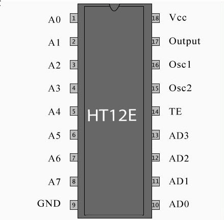
| Pin Diagram of IC HT12E |
HT12E is a 2^12 series encoder IC widely used in remote control and very common among Radio Frequency RF applications.This HT12E IC capable of converting 12 bit Parallel data inputs into serial outputs.These bits are classified into 8 (A0-A7) address bits and 4(AD0-AD3) data bits.Using the address pins we can provide 8 bit security code for secured data transmission between the encoder and the decoder.The encoder and decoder should use the same address and data format.HT12E is capable of operating in a wide Voltage range from 2.4V to 12V and also consists of a built in oscillator.Let's move into the working of HT12E encoder IC.
PIN DESCRIPTION OF IC HT12E:
The pin Description of the IC HT12E was pretty simple to understand with total of 18 pins.
- VDD and VSS:Positive and negative power supply pins.
- OSC1 and OSC2:Input and output pins of the internal oscillator present inside the IC.
- TE:This pin is used for enabling the transmission, a low signal in this pin will enable the transmission of data bits.
- A0 – A7:These are the input address pins used for secured transmission of this data.These pins can be connected to VSS for low signal or left open for high state.
- AD0 – AD3:This pins are feeding data into the the IC.These pins may be connected to VSS for sending LOW since it is a active low pin
- DOUT:The output of the encoder can be obtained through this pin and can be connected to the RF transmitter.
WORKING OF HT12E IC:
 HT12E starts working with a low signal on the TE pin.After receiving a low signal the HT12E starts the transmission of 4 data bits as shown in the timing diagram above.And the output cycle will repeats based on the status of the TE pin in the IC.If the TE pin retains the low signal the cycle repeats as long as the low signal in the TE pin exists.The encoder IC will be in standby mode if the TE pin is disabled and thus the status of this pin was necessary for encoding process.The address of these bits can be set through A0 – A7 and the same scheme should be used in decoders to retrieve the signal bits.
PRACTICAL CIRCUIT USING HT12E:

|
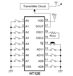
| Practical Application Circuit |
The above diagram shows the practical set up of the HT12E encoder IC for better understanding on the working.


Hello, I am working with this and a logic analyzer to see the modulation and any time I set one of the data pins low the whole ask modulation goes to zero even after leaving the rest of the address and data pins floating what might be the issue …thanks in advance.
hi frank will the voltage in the encoder ht12e dout pin become zero if I unground the input data..plz reply thanks in advance
The data pin is internally pulled high once it is ungrounded.
Hey Frank,
In the datasheet, it says that we can have 2^12 various combinations of addresses, which means 4096 different addresses we can make.
But pins AD8-AD11 are not address pins, so we have only 8 pins for address A0-A7, which can provide only 256 different addresses, so this IC is not good for production?is that right?
Dohab,
To be honest this is entirely up to your requirement.There are 256 address combinations which I feel will do a good job in securing the communication and keep away interference.However if you need to have more address combinations then you might want to look for other encoder-decoder pair available in the market.
thank you, can you suggest other encoder-decoder pair that provide bigger range of address?
I have 5v 12d cut and 12v 12e ckt .for d i use 51k register and for e 1meg te going to high but data not working pls gaide me collect data
Sachin,
I couldn't figure out what you are trying to ask.Kindly repost your question.
Calculating addresses, we are limited to 56 addresses per pair.Is that correct?if true, does it mean that we can't use it for production?if true, is there any alternatives to get more addresses?
Rod,
No we are limited to 256 address per pair.If you need more address I suggest you to look for any other encoders and decoders with more address combinations.
From a newbie:
Where are the input pins on the ic
I would like to connect a potentiometer to the input on the ic (for rc car)
Hi Ben,
There are two types of input pins address pins (A0 to A7) and Data pins (AD0 to AD3)